Are you wasting time and money annually calibrating BMS space temperature sensors
Temperature sensors do not need to be calibrated annually, really; they should almost never be calibrated. If your annual BMS maintenance contract includes for calibrating space temperature sensors, then you would be better off using that time on tasks that add value and saves energy.
BMS space temperature sensors are usually of the RTD type (resistance temperature device).
The sensing element is usually a semiconductor material that as the temperature changes its resistance changes. This change in resistance is measured by the BMS controller and converted into a temperature reading.
The sensing element is typically accurate to 0.2 Deg C, therefore, when a sensor appears to be reading incorrectly it is usually the result of some other influence and 'calibrating' the sensor just masks the underlying issue.
Less obvious issues that affect space temperature sensors
Because the temperature measurement is relative to resistance, and the cable wired between the sensor and the controller has a resistance, the length of the cable and its resulting resistance affects the calculation of temperature. Long cable runs and poor-quality cables can cause sensors to read incorrectly.
Often the cable entry hole, where the cable enters the sensor from the plasterboard wall, hasn't been blocked. This can result in a slight draft of warmer or cooler air, depending on the season, passing over the sensing element. Therefore, the technician is likely 'calibrating' or offsetting this slight draft temperature, which changes through the seasons.
Sensors installed directly onto concrete walls or columns can read a degree or two lower than the air temperature.
Offsetting cable resistance
Wire a fixed resister, for example 10,000 ohm, directly into the terminals of the controller analogue input and note down the temperature reading, for example 25°C. This is a fixed, known temperature reading without any influence of resistance due to cable length as the resister is wired directly into the controller.
Now, walk over to where the temperature sensor is installed, disconnect the temperature sensor and connect the 10,000-ohm resister onto the end of the cable. The difference in what the BMS is now reading from 25°C is the result of additional resistance introduced by the cable. Offset or 'calibrate' the BMS controller analogue input to read 25°C.
When done properly, ideally during the construction phase, you technically never need to offset the sensor cable ever again.
Issues when calibrating using a reference thermometer
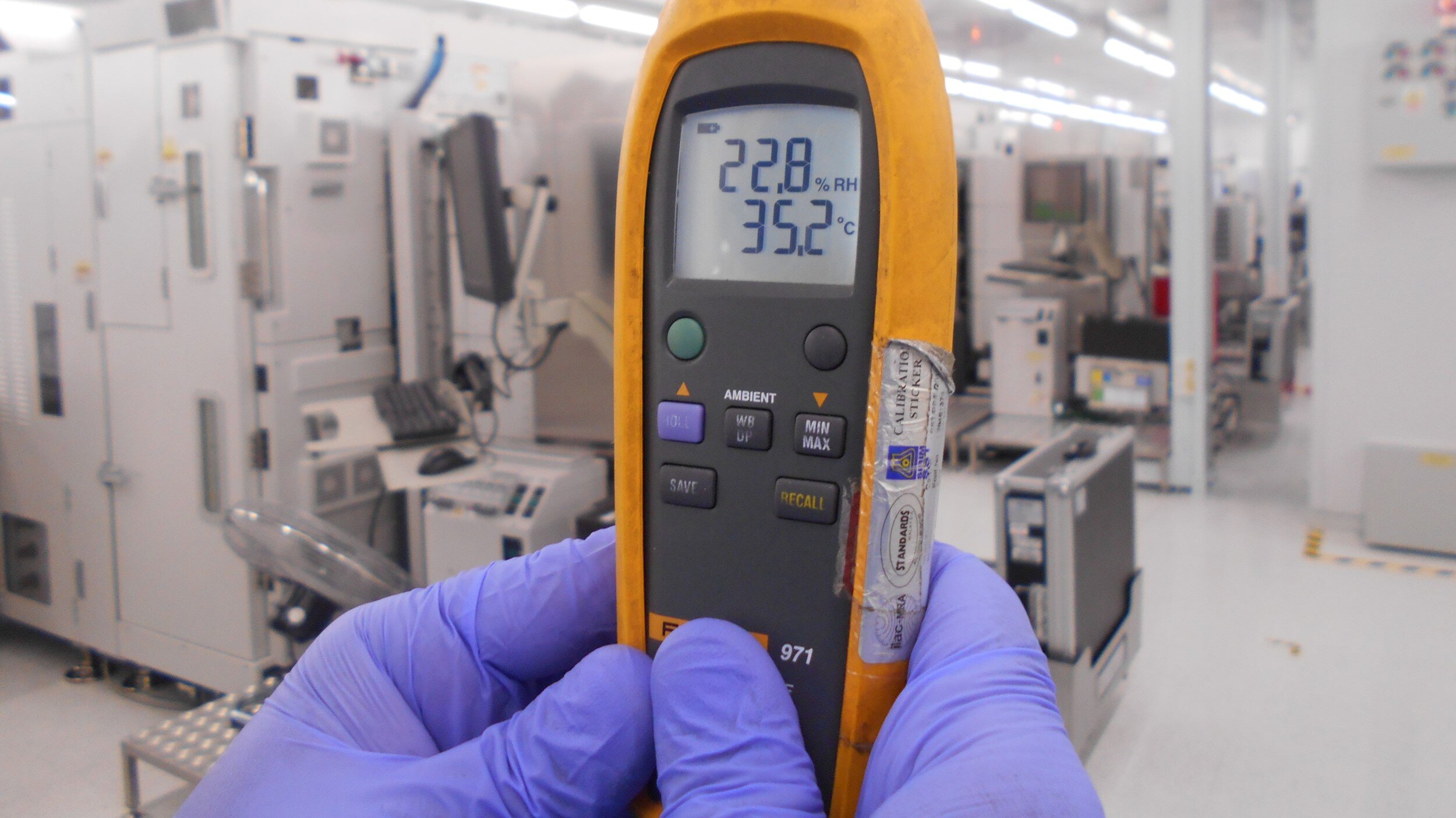
There are many issues when calibrating a space temperature sensor using a handheld reference thermometer rather than doing the cable resistance offset method described above.
Before taking a reading, the technician should wait until the reference thermometers sensing element has stabilised after walking around with it. Ideally, the thermometer should be hung over the space temperature sensor and left to stabilise for at least 5 minutes. If calibrating a whole floor, it is likely that impatience will kick in, which means the sensor will be calibrated against the wrong temperature.
Technically, a sensor should be calibrated or checked at two points not just at one point, this isn't possible outside of a laboratory, although a minor point, it adds to the argument not to directly calibrate space temperature sensors.
Good quality installation
Like most things, if we just did it properly the first time, we wouldn't have half the issues we have.
A good quality sensor cable with a minimum of 0.5mm cross-section area conductors will reduce the effect of cable resistance issues. I have seen on many occasions when doing site inspections, 0.2mm cables or even Cat5 Ethernet cables used for sensors.
A well-designed installation where space temperature sensor cable lengths are kept below 30 meters will reduce the effect of cable resistance.
The cable entry hole is blocked with silicon or similar.
I personally haven't seen proven issues of voltage induction from other cables, but keeping low voltage cables away from mains voltage cables, for example motor cables and 240Vac power supplies, will reduce any interference.
Providing screened cables, earthed at the controller end only, will assist in reducing the effect of induction and interference from other mains voltage cables.
I would even go as far to say, that if properly installed, that the sensor or cable doesn't need to be calibrated at all. I would spot check a couple of cable resistances, and if low, wouldn't even bother with offsetting the cable resistance.
If a sensor is reading inaccurately by more than say 2°C and you don't have any physical issues, then the sensor should be replaced, not calibrated. Calibrating a faulty sensor or calibrating out an installation issue just makes it look right on the graphics, it usually doesn't fix anything.
Use the saved maintenance time by not calibrating temperature sensors annually on something that makes a difference, adds value and saves energy.
Featured - Latest published online course

BMS for mechanical consultants course
This course was developed by a BMS consultant for mechanical consultants involved in Building Management System projects. Learn how to reduce risk to your company, your client, and the BMS contractor.
Self-paced online course.
12 hours of video lessons.
Training manual (+90 pages).
BMS design examples.
A sample of Lifecycle Controls BMS specification clauses are provided to assist with learning. You can use these in your own specification.
Online shop


Free control strategy mini courses
Create a free account in our Learning Management System and complete the free chilled water control system mini-course. A certificate is provided at the end of the course. A copy of the control strategy is provided as a Microsoft Word document for you to modify in your own BMS designs.

Please join our newsletter
To be notified when new courses, design templates, and digital products are published.
For updates to coaching availability.
For updates to business-to-business consulting services.
New Youtube video releases and occasional updates on what I am up to.
I will not fill up your inbox with crap.

Bryce Anderson
I am an independent Building Management System consultant based in Australia. I started in the BMS industry in 1998 and initially worked for BMS companies for the first 15 years of my career (2 years in South Africa, 9 years in London, and 4 years in Melbourne). In 2014 I transitioned into BMS consulting, saw a massive gap in the lack of specialist BMS consulting, and started Lifecycle Controls in 2017.
My focus is currently on BMS technical training, coaching, and B2B consulting for BMS companies and mechanical consultancies. Because, fixing one project at a time was making no difference. Training thousands of engineers will :-)